Type E Bearings Overview
Heavy Duty Royersford "Type E" Bearings come in a wide range of sizes and styles offering many advantages including high speed suitability, ruggedness, positive locking to the shaft, and at a competitive price.
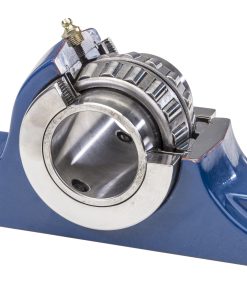
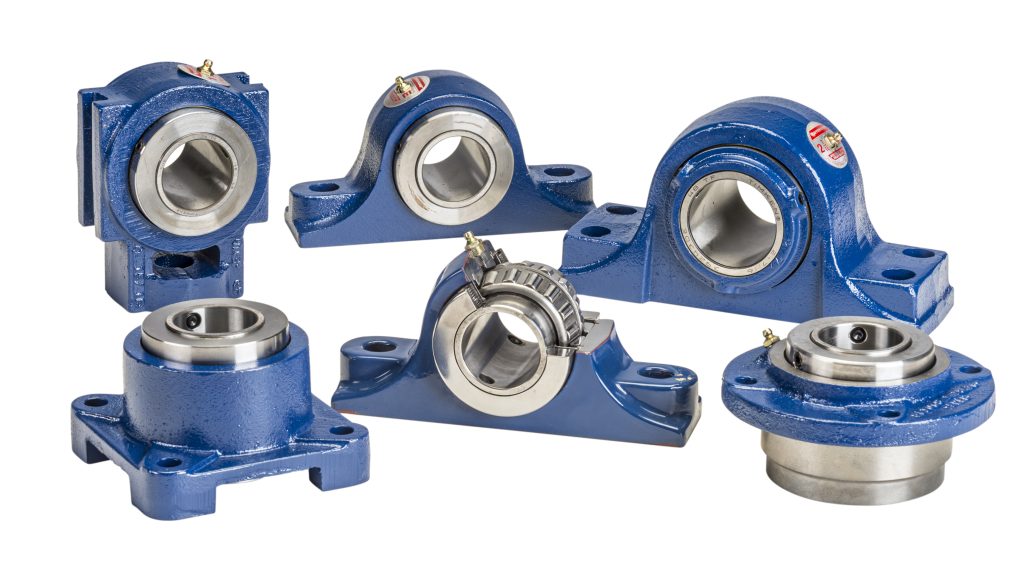
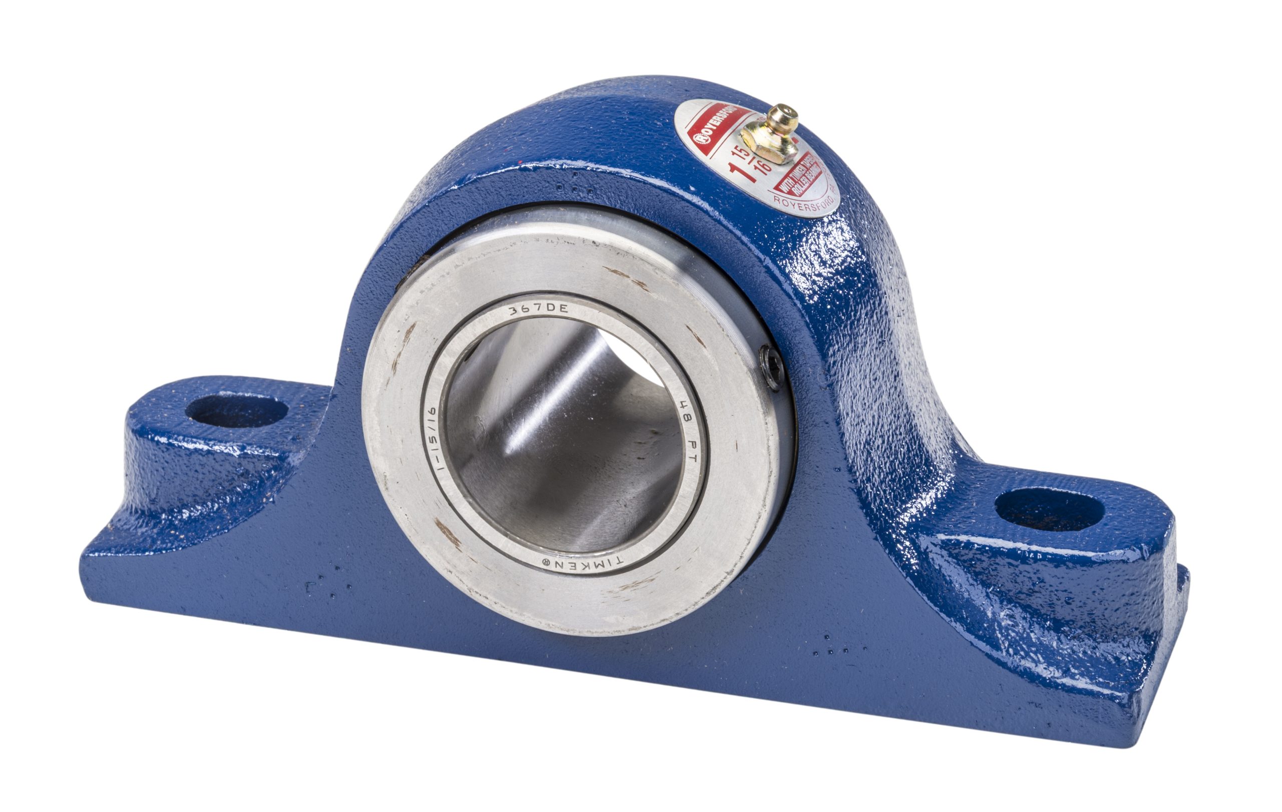
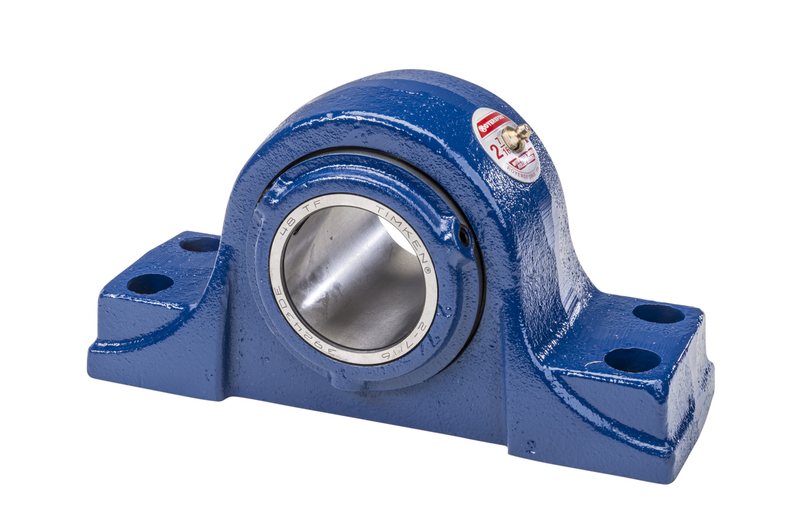
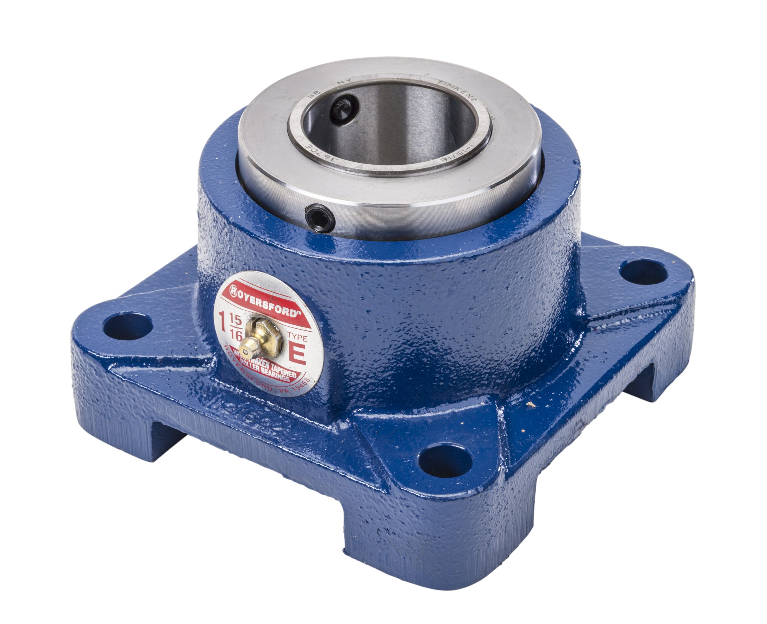
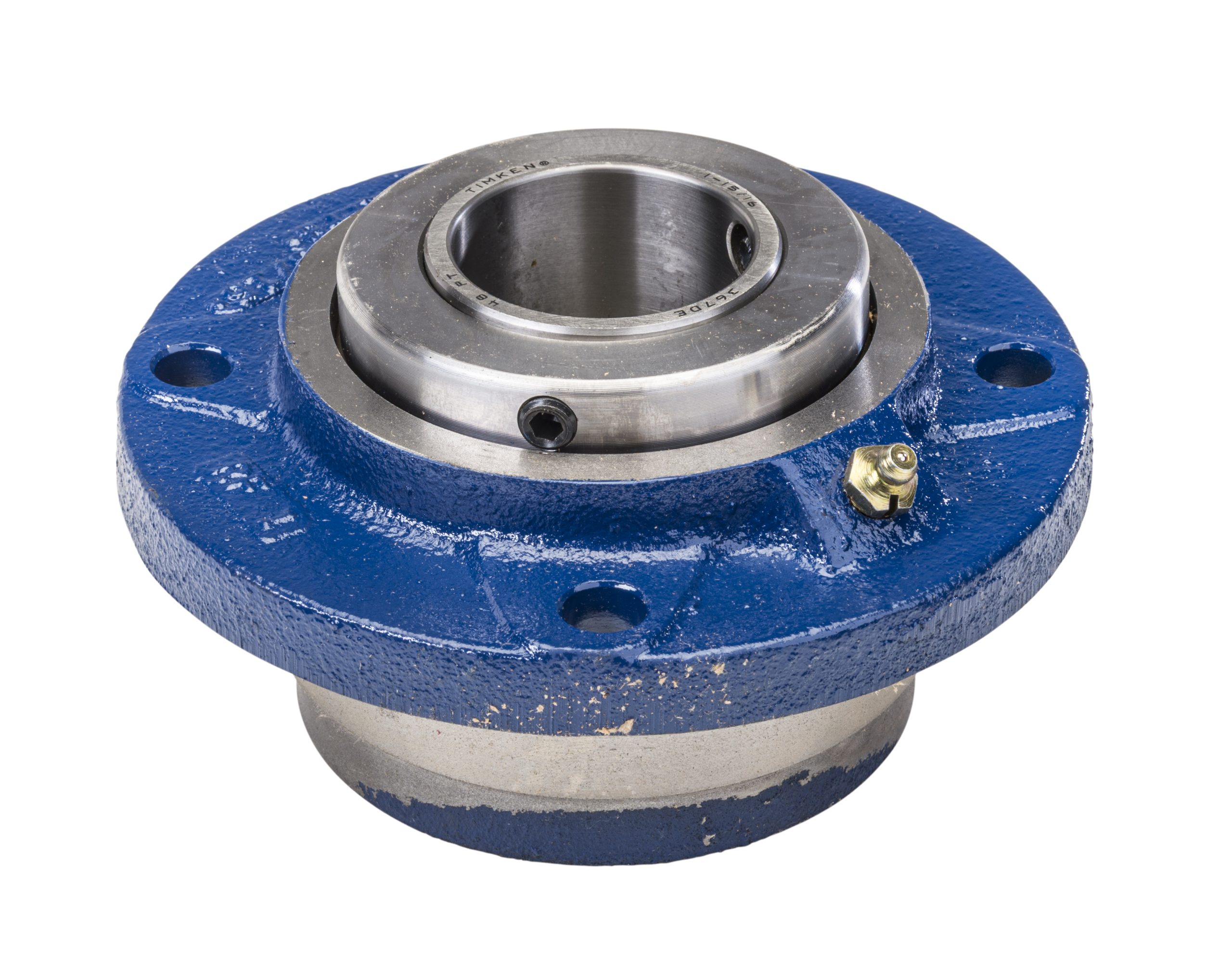
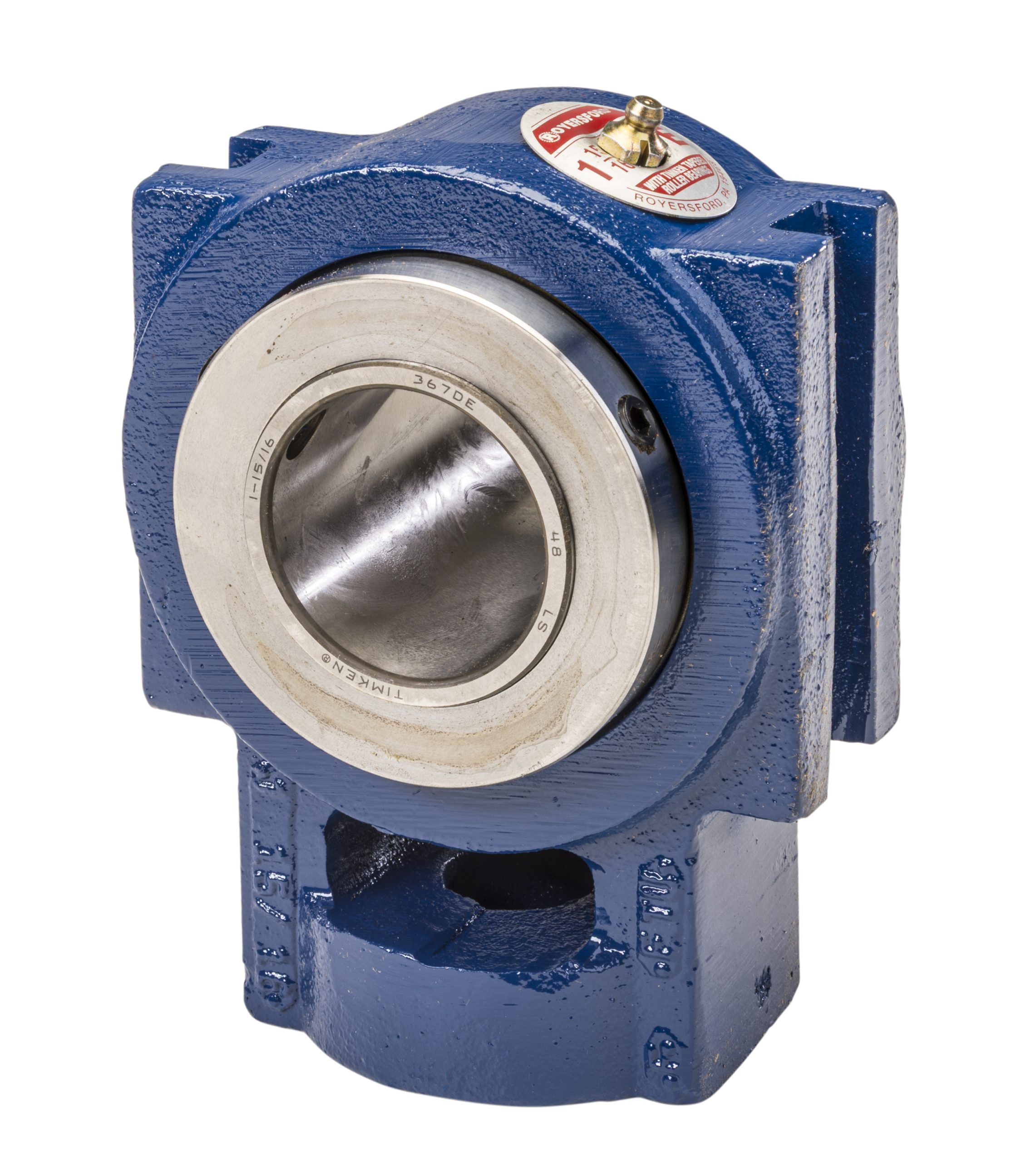
The high strength grey iron housings are designed to be compact without sacrificing ruggedness. They are available in two and four bolt base Pillow Blocks, Square Flange, Piloted Flange and Take-Up styles; all mounting surfaces are fully machined to close tolerances. Both ends use positive locking ductile iron collars to securely fasten the inner race to the shaft. Two set screws are used for additional holding power.
Timken Tapered Roller Bearings are used exclusively in Royersford "Type E" Bearings. These superior quality bearings are made from vacuum degassed steel which gives races and rollers unsurpassed load handling capabilities and longer useful bearing life. Load distribution is balanced over a long inner race giving the bearings a high radial and thrust load capacity suitable for most applications. The arrangement of the Timken rollers and races enables a slight angular misalignment to be handled.
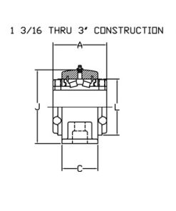
Snap rings and shims are used for proper race adjustment on sizes thru 3". For sizes 3-3⁄16" thru 5" an adjusting nut is used. Bore tolerance is +.001" - .000" for 3" and smaller bores; and +.002" - .000" for bores larger than 3". Royersford "Type E" Bearings are prelubricated, adjusted and sealed at the factory. Just slip the bearings on the shaft. Danger from bearing failure caused by dirt or contaminants during installation is eliminated. Shaft ready bearings save time and expense as well as the possibility of premature failure present when housings must be cleaned, adjusted and lubricated during installation. Reduced expenses on installation and long life enable overall operating benefits that do not exist with other type bearings.
Dual lip medium contact seals....built in at each end of the bearing during factory assembly....offer the advantage of a primary lip that prevents loss of lubricant and a secondary lip for dirt and dust exclusion, both before and after installation of the bearing on the shaft. Sealing efficiency is maintained throughout the full range of self-alignment. Dual locking collars act as rotating fingers to keep contaminants away from the seals, further increasing the seal efficiency.
Royersford "Type E" Bearings are carried in warehouse and distributor stocks in popular transmission shaft sizes from 1-3⁄16" to 5".
Type E Bearing Products
Selection
Royersford "Type E" tapered-roller bearings have the capacity to carry heavy radial loads, thrust loads and combined radial/thrust loads. The maximum recommended load which can be applied is limited by various components in the system, such as bearing, housing, shaft, shaft attachment, speed and life requirements as listed in this catalog.
Select a bearing from the "Type E" Selection Chart having a radial load rating at operating speed equal to or greater than the calculated "Equivalent Radial Load" for a desired L10 Life. This simple method is all that is required for the majority of general applications and provides for occasional average shock loads. (Equivalent Radial Load = P.)
L10 Hours Life - is the life which may be expected from at least 90% of a given group of bearings operating under identical conditions.
For a L10 Hours Life other than those listed in the selection chart, multiply the Equivalent Radial Load by one of the following factors. For 50,000 L10 Hours Life use factor of 1.16; 80,000, 1.34. Then select a bearing from the bold face (30,000) L10 ratings only in the selection chart having rating equal to or greater than this value.
Heavy Service - For heavy shock loads, frequent shock loads or severe vibrations, add up to 50% (according to severity of conditions) to the Equivalent Radial Load to obtain a Modified radial Load.
Thrust load values shown in the table below are recommended as a guide for general applications that will give adequate L10 Life. Where substantial radial load is also present, it is advisable to calculate the L10 Life to assure it meets the requirements. The maximum thrust load should not exceed the limits shown in the table labeled "Allowable Thrust-Pillow Block Housings." The effectiveness of the shaft attachment to carry thrust load depends on proper tightening of the setscrews, shaft tolerance, and shaft deflections. Therefore, it is advisable to use auxiliary thrust carrying devices such as shaft shoulder, snap ring, or a thrust collar to locate the bearing under heavier thrust loads or where extreme reliability is desired.
The shaft tolerances recommended are adequate for normal radial, thrust, and radial/thrust load applications. The radial load is limited by the attachment to the shaft (see Table 1). Since the allowable load, especially at low speed, is very large, the shaft should be checked to assure adequate shaft strength.
The magnitude and direction of both the thrust and radial load must be taken into account when selecting a housing. When pillow blocks are utilized, heavy loads should be directed through the base. Where a load pulls the housing away from the mounting base, both the hold-down bolts and housing must be of adequate strength. Auxiliary load carrying devices such as shear bars are advisable for side or end loading of pillow blocks and radial loads for flange units. To determine the L10 Hours Life for loads and RPM's not listed, use the following equation:
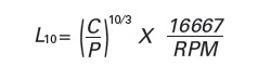
Where:
- L 10 = Life hours
- C90 = Dynamic Capacity, lbs. (Table 1)
- P = Equivalent Radial Load, lbs.
When the load on a two row roller bearing is solely a radial load with no thrust (axial) load, the load is shared equally by both rows of rollers and the equivalent radial load (P) is equal to the actual radial load. However, when a thrust (axial) load is applied, the loading on the two rows is shared unequally depending on the ratio of thrust to radial load. The use of the X (radial factor) and Y (thrust factor) from Table 1 convert the actual applied thrust and radial loads to an equivalent radial load which has the same effect on the life of a bearing as a radial load of the magnitude.
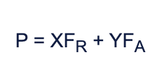
Where:
- P = Equivalent radial load, lbs.
- F R = Radial load, lbs. - (See Table 1 for allowable slip fit maximum)
- F A = Thrust (axial) load, lbs.
- e = Thrust load to radial load factor (Table 1)
- X = Radial Load Factor from table 1
- Y = Thrust Load Factor from table 1
To find X and Y, first calculate FA/FR and compare to e. Determine X and Y from Table 1. Light thrust FA/FR less than or equal to e or heavy thrust FA/FR greater than e.
Substitute all known values into the equivalent radial load equation. The equivalent radial load (P) thus determined can be used in the L10 life formula or compared to the allowable equivalent radial load rating desired in the expanded rating table below to select a bearing.
If calculated value of P is less than FR use P = FR.
Table 1 - Radial/Thrust Factors
|
Shaft |
e |
FA/FR < or = e |
FA/FR > e |
Dynamic Capacity |
Maximum |
Maximum Slip Fit Radial |
|||
|---|---|---|---|---|---|---|---|---|---|
| X | Y | X | Y | Lbs. | Newtons | ||||
|
1 3⁄16 - 1 1⁄4 |
.49 | .87 | 1.77 | .70 | 2.14 | 2.980 | 13.260 | 4.490 | 3,100 |
|
1 3⁄8 - 1 7⁄16 |
.46 | .87 | 1.89 | .70 | 2.28 | 4.760 | 21.180 | 3.820 | 5,000 |
|
1 1⁄2 - 1 11⁄16 |
.44 | .87 | 1.96 | .70 | 2.37 | 6.140 | 27.320 | 3.320 | 6,400 |
|
1 3⁄4 - 2 |
.33 | .87 | 2.64 | .70 | 3.18 | 8.070 | 35.908 | 3.050 | 8,400 |
|
2 3⁄16 |
.36 | .87 | 2.38 | .70 | 2.87 | 8.550 | 38.044 | 2.730 | 8,900 |
|
2 1⁄4 - 2 1⁄2 |
.40 | .87 | 2.17 | .70 | 2.63 | 9.090 | 40.447 | 2.420 | 9,500 |
|
2 11⁄16 - 3 1⁄2 |
.46 | .87 | 1.87 | .70 | 2.26 | 9.600 | 42.716 | 2.060 | 10,000 |
|
3 3⁄16 - 3 1⁄2 |
.50 | .87 | 1.71 | .70 | 2.07 | 15.300 | 68.078 | 1.640 | 16,000 |
|
3 15⁄16 - 4 |
.49 | .87 | 1.77 | .70 | 2.14 | 21.000 | 93.440 | 1.530 | 22,000 |
|
4 7⁄16 - 4 1⁄2 |
.53 | .87 | 1.63 | .70 | 1.97 | 25.800 | 114.799 | 1.360 | 27,000 |
|
4 15⁄16 - 5 |
.47 | .87 | 1.83 | .70 | 2.21 | 35.500 | 157.959 | 1.200 | 35,000 |
Table 2 - Allowable Thrust - Pillow Block Housing
|
Bore Size |
1 3⁄16 - 1 1⁄4 |
1 3⁄8 - 1 7⁄16 |
1 1⁄2 - 1 11⁄16 |
1 3⁄4 - 2 |
2 3⁄16 |
2 1⁄4 - 2 1⁄2 |
2 11⁄16 - 3 |
3 3⁄16 - 3 1⁄2 |
3 15⁄16 - 4 |
4 7⁄16 - 4 1⁄2 |
4 15⁄16 - 5 |
|---|---|---|---|---|---|---|---|---|---|---|---|
| 2 - Bolt | 1300 | 2200 | 2200 | 2300 | 3300 | 3300 | 4500 | 5500 | ----- | ----- | ----- |
| 4 - Bolt | ----- | ----- | ----- | ----- | 3300 | 3300 | 4500 | 16500 | 14600 | 13400 | 10600 |
*C90 - Dynamic capacity based on a rated life of 90 million revolutions or 3000 hours at 500 RPM.
**If load exceeds maximum allowable slip fit radial load (FR), line to the t-light press fit of shaft required. Maximum slip fit radial loads are recommended shaft tolerances are used.
Table 3 - Radial Load Ratings in Pounds
|
Dynamic Capacity C90 |
Shaft |
L10 |
Allowable Equivalent Radial Load Ratings (lbs.) at Various Revolutions Per Minute |
|||||||||||||||
|---|---|---|---|---|---|---|---|---|---|---|---|---|---|---|---|---|---|---|
| LBS | Newtons | 10 | 25 | 50 | 100 | 250 | 500 | 750 | 1000 | 1250 | 1500 | 1750 | 2000 | 2500 | 3000 | 3500 | ||
| 3040 | 13523 |
1 3⁄16 1 1⁄4 |
10,000 | 6850 | 5204 | 4227 | 3433 | 2608 | 2118 | 1876 | 1721 | 1609 | 1524 | 1455 | 1398 | 1307 | 1238 | 1182 |
| 30,000 | 4927 | 3743 | 3040 | 2469 | 1876 | 1524 | 1349 | 1238 | 1157 | 1096 | 1046 | 1005 | 940 | 890 | 850 | |||
| 40,000 | 4519 | 3433 | 2789 | 2265 | 1721 | 1398 | 1238 | 1135 | 1062 | 1005 | 960 | 922 | 862 | 816 | 780 | |||
| 60,000 | 4002 | 3040 | 2469 | 2006 | 1524 | 1238 | 1096 | 1005 | 940 | 890 | 850 | 816 | 764 | 723 | 690 | |||
| 100,000 | 3433 | 2608 | 2118 | 1721 | 1307 | 1062 | 940 | 862 | 807 | 764 | 729 | 700 | 655 | 620 | 592 | |||
| 4860 | 2168 |
1 3⁄8 1 7⁄16 |
10,000 | 10951 | 8319 | 6757 | 5489 | 4169 | 3387 | 2999 | 2751 | 2573 | 2436 | 2326 | 2234 | 2090 | 1978 | 1889 |
| 30,000 | 7876 | 5983 | 4860 | 3948 | 2999 | 2436 | 2157 | 1978 | 1850 | 1752 | 1673 | 1607 | 1503 | 1423 | 1359 | |||
| 40,000 | 7225 | 5489 | 4458 | 3621 | 2751 | 2234 | 1978 | 1815 | 1697 | 1607 | 1534 | 1474 | 1379 | 1305 | 1246 | |||
| 60,000 | 6398 | 4860 | 3948 | 3206 | 2436 | 1978 | 1752 | 1607 | 1503 | 1423 | 1359 | 1305 | 1221 | 1156 | 1104 | |||
| 100,000 | 5489 | 4169 | 3387 | 2751 | 2090 | 1607 | 1503 | 1379 | 1289 | 1221 | 1166 | 1120 | 1047 | 992 | 947 | |||
| 6260 | 27846 |
1 1⁄2 1 5⁄8 1 11⁄16 |
10,000 | 14106 | 10716 | 8704 | 7070 | 5371 | 4362 | 3863 | 3637 | 3314 | 3137 | 2996 | 2878 | 2692 | 2548 | ----- |
| 30,000 | 10145 | 7707 | 6260 | 5085 | 3863 | 3137 | 2778 | 2548 | 2383 | 2257 | 2155 | 2070 | 1936 | 1833 | ----- | |||
| 40,000 | 9306 | 7070 | 5742 | 4664 | 3543 | 2878 | 2548 | 2370 | 2186 | 2070 | 1976 | 1899 | 1776 | 1681 | ----- | |||
| 60,000 | 8241 | 6260 | 5085 | 4130 | 3137 | 2548 | 2257 | 2070 | 1936 | 1833 | 1752 | 1681 | 1572 | 1489 | ----- | |||
| 100,000 | 7070 | 4362 | 3543 | 2924 | 2692 | 2186 | 1936 | 1776 | 1661 | 1572 | 1501 | 1442 | 1349 | 1277 | ----- | |||
| 8230 | 36609 |
1 3⁄4 1 7⁄8 1 15⁄16 2 |
10,000 | 18545 | 14088 | 11443 | 9295 | 7061 | 5735 | 5078 | 4658 | 4357 | 4125 | 3938 | 3784 | 3539 | 3350 | ----- |
| 30,000 | 13338 | 10132 | 8230 | 6685 | 5078 | 4125 | 3652 | 3330 | 3133 | 2967 | 2833 | 2721 | 2545 | 2410 | ----- | |||
| 40,000 | 12235 | 9235 | 7550 | 6132 | 4658 | 3784 | 3350 | 2967 | 2874 | 2721 | 2598 | 2496 | 2335 | 2210 | ----- | |||
| 60,000 | 10834 | 8230 | 6685 | 5430 | 4125 | 3350 | 2967 | 2721 | 2545 | 2410 | 2301 | 2210 | 2067 | 1957 | ----- | |||
| 100,000 | 9295 | 7061 | 5735 | 4658 | 3539 | 2874 | 2545 | 2335 | 2184 | 2067 | 1974 | 1896 | 1774 | 1679 | ----- | |||
| 8720 | 38788 |
2 3⁄16 |
10,000 | 19649 | 14927 | 12124 | 9848 | 7481 | 6076 | 5381 | 4910 | 4616 | 4370 | 4173 | 4009 | 3749 | ----- | ----- |
| 30,000 | 14132 | 10736 | 8720 | 7083 | 5381 | 4370 | 3807 | 3550 | 3320 | 3143 | 3001 | 2883 | 2697 | ----- | ----- | |||
| 40,000 | 12964 | 9858 | 7999 | 6493 | 4970 | 3955 | 3500 | 3312 | 3056 | 2883 | 2753 | 2645 | 2474 | ----- | ----- | |||
| 60,000 | 11479 | 8720 | 7083 | 5753 | 4370 | 3550 | 3143 | 2883 | 2673 | 2533 | 2438 | 2342 | 2190 | ----- | ----- | |||
| 100,000 | 9848 | 7481 | 6076 | 4984 | 3749 | 3045 | 2697 | 2474 | 2314 | 2190 | 2091 | 2009 | 1879 | ----- | ----- | |||
| 9270 | 41235 |
2 1⁄4 2 7⁄16 2 1⁄2 |
10,000 | 20888 | 15868 | 12889 | 10469 | 7953 | 6460 | 5720 | 5247 | 4907 | 4646 | 4436 | 4262 | 3986 | ----- | ----- |
| 30,000 | 15023 | 11413 | 9270 | 7530 | 5720 | 4646 | 4114 | 3774 | 3529 | 3342 | 3191 | 3065 | 2867 | 2630 | ----- | |||
| 40,000 | 13723 | 10469 | 8504 | 6907 | 5247 | 4262 | 3774 | 3462 | 3238 | 3065 | 2927 | 2812 | 2663 | ----- | ----- | |||
| 60,000 | 12203 | 9270 | 7530 | 6116 | 4646 | 3774 | 3342 | 3070 | 2892 | 2714 | 2591 | 2490 | 2329 | ----- | ----- | |||
| 100,000 | 10469 | 7953 | 6460 | 5247 | 3986 | 3238 | 2867 | 2630 | 2459 | 2329 | 2223 | 2136 | 1998 | ----- | ----- | |||
| 9790 | 43548 |
2 11⁄16 2 3⁄4 2 15⁄16 3 |
10,000 | 22066 | 16758 | 13612 | 11056 | 8399 | 6822 | 6041 | 5541 | 5182 | 4907 | 4685 | 4501 | ----- | ----- | ----- |
| 30,000 | 15806 | 12053 | 9790 | 7952 | 6041 | 4907 | 4345 | 3727 | 3529 | 3369 | 3237 | ----- | ----- | ----- | ----- | |||
| 40,000 | 14564 | 11056 | 8981 | 7294 | 5541 | 4501 | 3985 | 3656 | 3419 | 3237 | 3091 | 2969 | ----- | ----- | ----- | |||
| 60,000 | 12887 | 9790 | 7952 | 6459 | 4907 | 3985 | 3529 | 3286 | 3028 | 2866 | 2737 | 2629 | ----- | ----- | ----- | |||
| 100,000 | 11056 | 8399 | 6822 | 5541 | 4209 | 3419 | 3028 | 2759 | 2597 | 2459 | 2348 | 2256 | ----- | ----- | ----- | |||
| 15600 | 69392 |
3 3⁄16 3 1⁄4 3 7⁄16 3 1⁄2 |
10,000 | 35152 | 26704 | 21690 | 17618 | 13384 | 10871 | 9626 | 830 | 8258 | 7819 | 7465 | ----- | ----- | ----- | ----- |
| 30,000 | 25286 | 19206 | 15600 | 12671 | 9626 | 7819 | 6923 | 5939 | 5623 | ----- | ----- | ----- | ----- | ----- | ----- | |||
| 40,000 | 23139 | 17618 | 14310 | 11523 | 8830 | 7172 | 6351 | 5548 | 5182 | ----- | ----- | ----- | ----- | ----- | ----- | |||
| 60,000 | 20536 | 15600 | 12671 | 10292 | 7819 | 6351 | 5623 | 4824 | 4568 | ----- | ----- | ----- | ----- | ----- | ----- | |||
| 100,000 | 17618 | 13384 | 10871 | 883 | 6708 | 5448 | 4824 | 4139 | 3919 | ----- | ----- | ----- | ----- | ----- | ----- | |||
*"Minimum Hours Life" is the life which may be expected from at least 90% of a given group of bearings operating under identical conditions. The average life will be approximately five times the minimum life.
Note: Because the allowable loads, especially at low speeds, are extremely high, be sure that the shaft strength is adequate and pillow blocks are base loaded. When the load line falls outside the base, fastener and housing deflection or failure may occur. These conditions require designs using proper engineering principles applied to materials, fasteners, mounting and etc. with adequate safety factors.