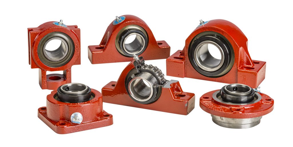
R2000 Bearings Overview
Royersford R2000 Mounted Spherical Bearings are suitable for a wide variety of applications. They work extremely well in situations where a high capacity alignable bearing is required. They are available in a wide range of shaft sizes and a variety of mounts.
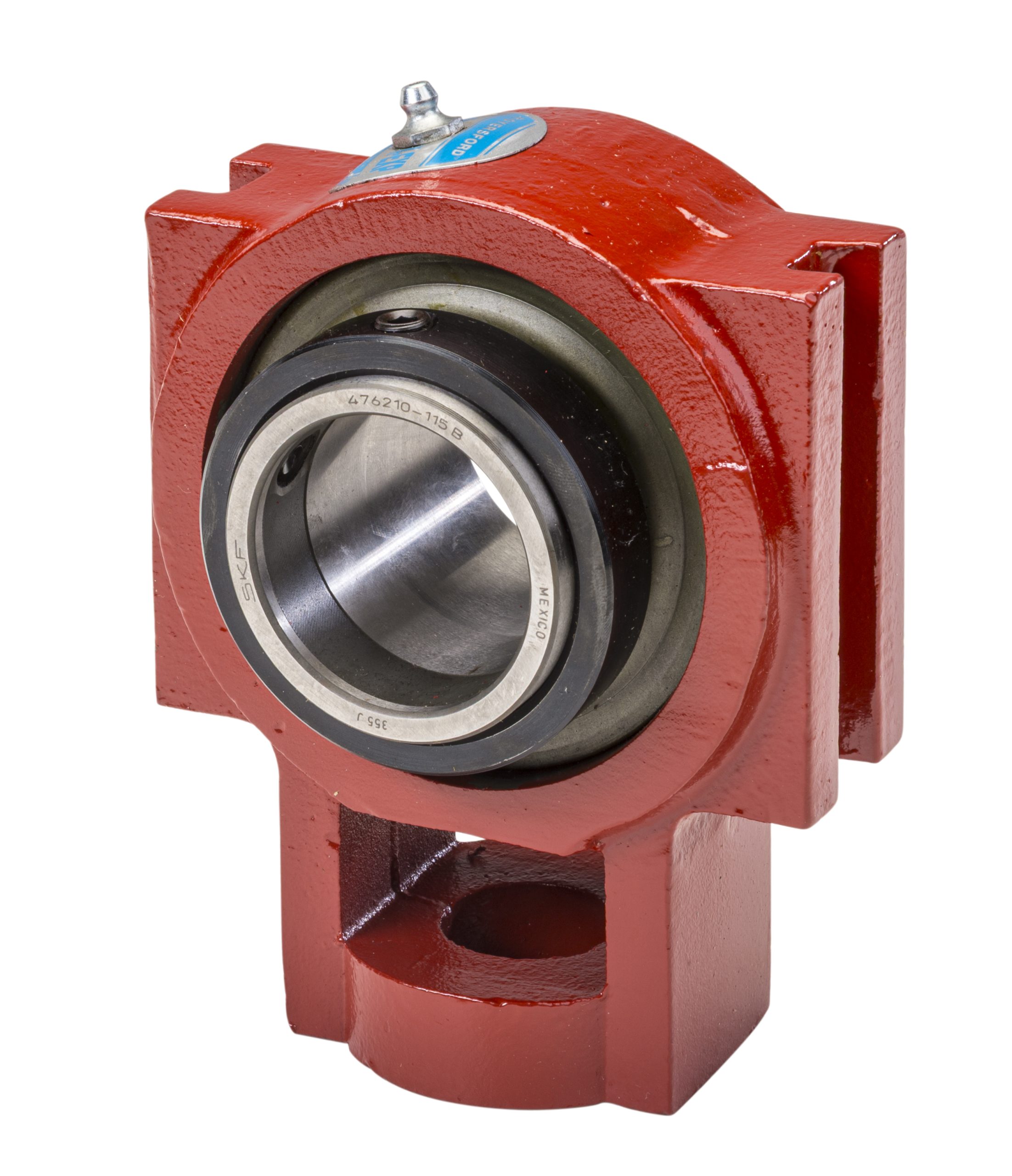
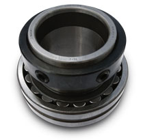
SKF® spherical bearing units are used exclusively in the Royersford R2000 series of bearings. They are capable of handling heavy radial and axial loads, running and static misalignment and high operating temperatures.
These bearings are completely assembled, sealed & lubricated at the factory so they are ready for use right from the box. The self-aligning feature provides for rapid mounting with a minimum of adjustment. The high strength grey iron housings are designed to be compact without sacrificing ruggedness.
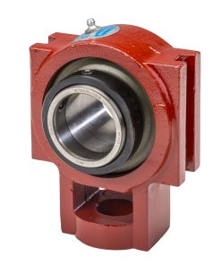
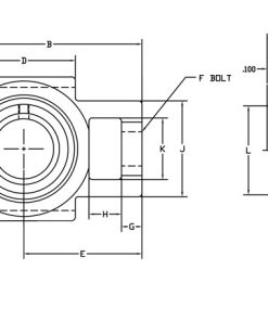
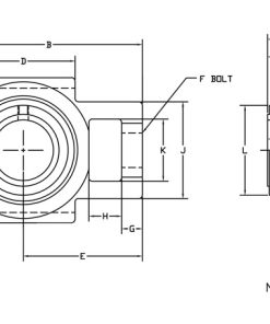
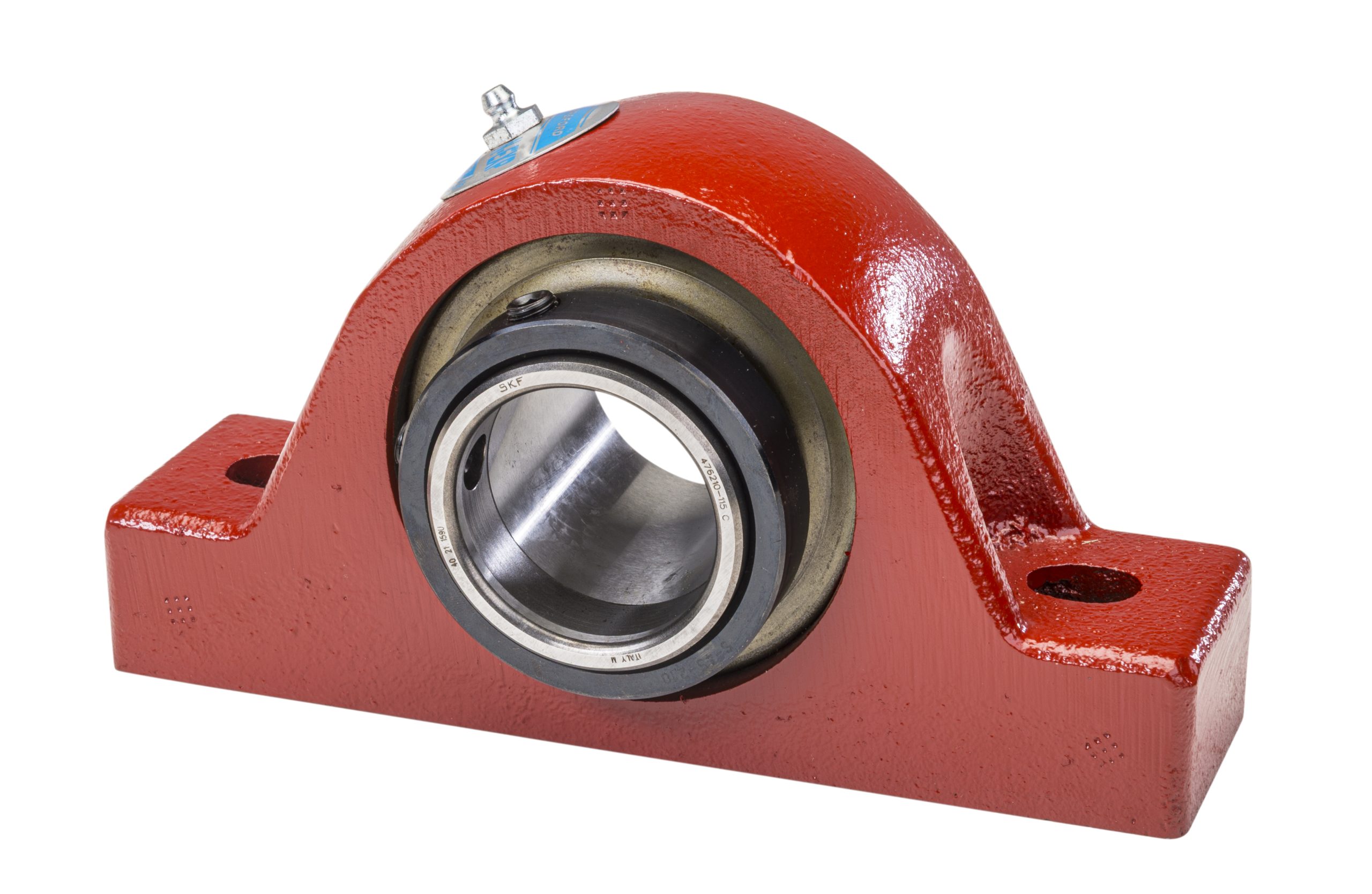
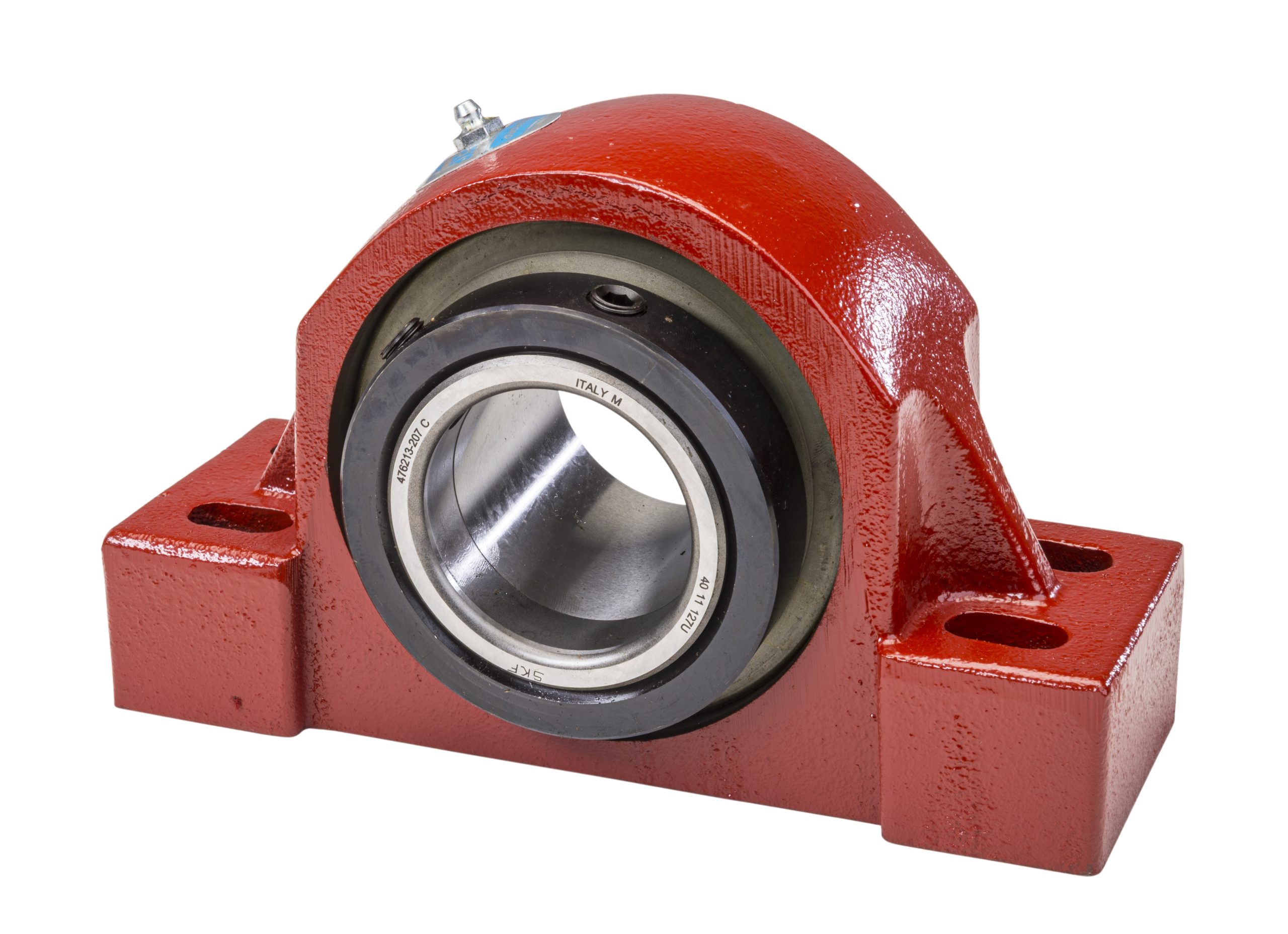
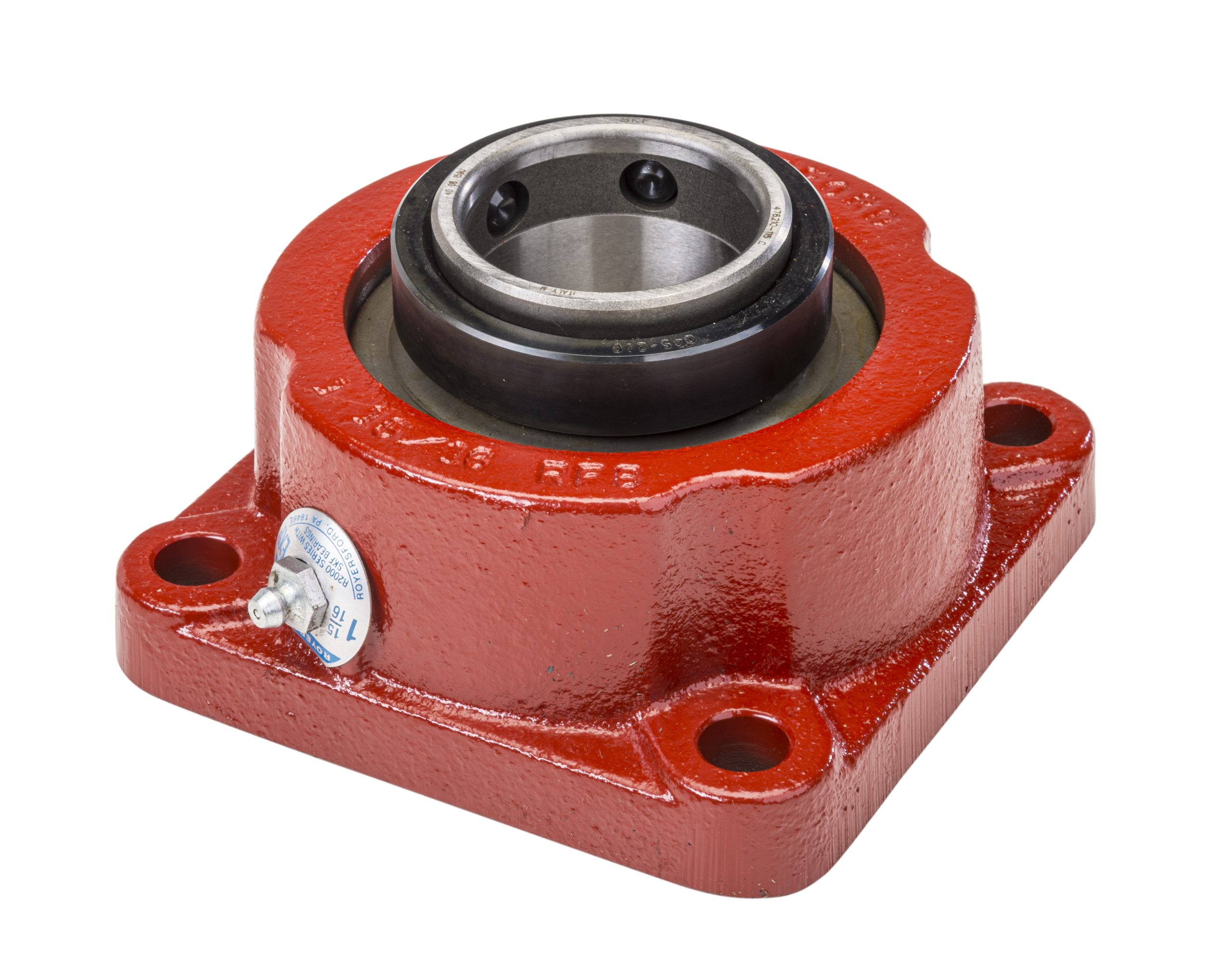
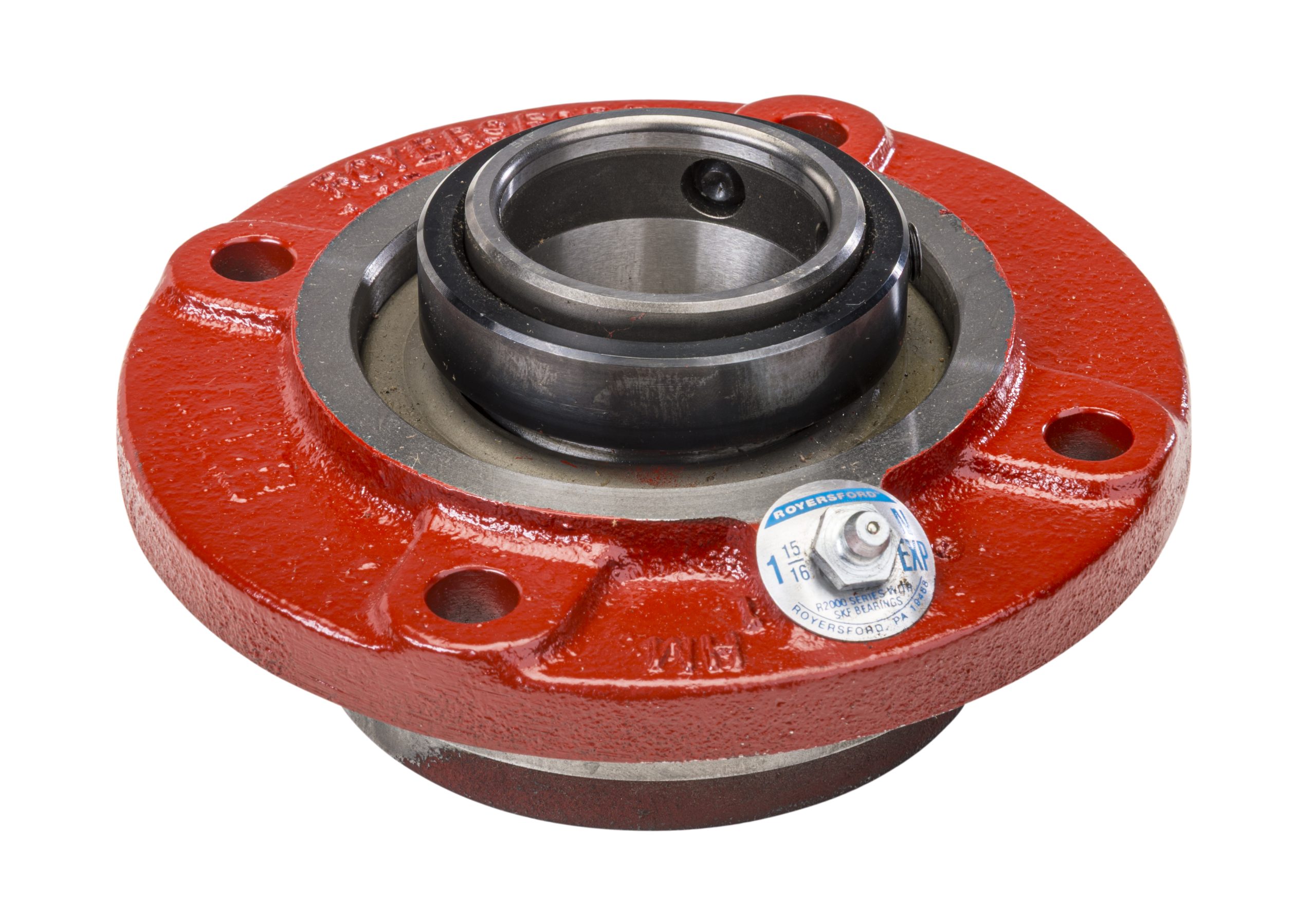
The R2000 are available in two and four bolt Pillow Blocks, Square Flange, Piloted Flange and Wide Slot Take-up styles. All sizes and styles are available in both non-expansion and expansion types. The expansion units have the capacity to move .100". Both can handle misalignment up to ± 1 ½ deg.
All R2000 bearings come with a specially designed double lip seal that prohibits the entry of contaminants, retains lubrication and is self-purging. Royersford R2000 Bearings come in shaft sizes from 1 7⁄16" thru 5" and are available from warehouses and distributor stocks throughout the United States and Canada.
R2000 Bearing Products
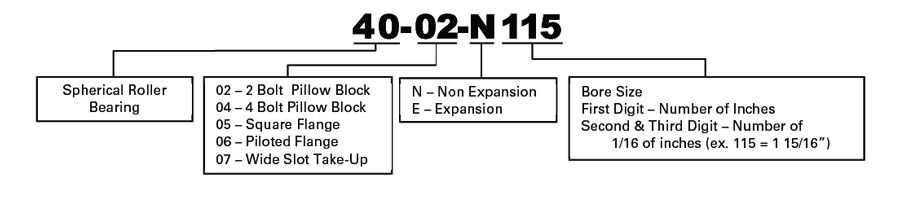
Spherical Roller Bearing Nomenclature
Selection
Royersford R2000 Spherical Roller Bearings have the capacity to carry substantial radial loads, thrust loads and combined radial/thrust loads. The maximum recommended load which can be applied is limited by the various components of the system, such as bearing, housing, shaft, shaft attachment, speed and life requirements as listed in this catalog.
Select a bearing from the R2000 Selection Chart having a radial load rating at the operating speed equal to or greater than the calculated "Equivalent Radial Load" for a desired L10 Life. This simple method is all that is required for a majority of general applications and provides for occasional average shock loads.
Basic Bearing Load Ratings:
|
Shaft Size |
Dynamic Capacity | Static Capacity |
|---|---|---|
| 1 7⁄16 1 1⁄2 |
16,600 | 18,300 |
|
1 11⁄16 |
17,300 |
19,800 |
| 1 15⁄16 2 |
19,000 | 22,500 |
|
2 3⁄16 |
22,400 |
26,500 |
| 2 7⁄16 2 1⁄2 |
33,300 | 41,100 |
|
2 11⁄16 |
35,500 |
46,800 |
| 3 3⁄16 3 7⁄16 3 1⁄2 |
56,900 | 76,400 |
|
3 15⁄16 |
69,900 |
93,300 |
| 4 7⁄16 4 1⁄2 |
91,700 | 126,000 |
| 4 15⁄16 5 |
123,000 |
180,000 |
L10 Hours of Life – is the life that may be expected from at least 90% of a given group of bearings operating under identical conditions. To determine L10 hours for loads & RPM's not listed, use the following equation:
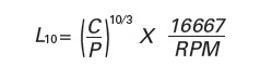
Where:
- L 10 = Life hours
- C = Dynamic Capacity (from table 1)
- P = Equivalent Radial Load
If the load on a double row spherical bearing is only in the radial direction (no axial load), the Equivalent Radial Load (P) is equal to the actual radial load. In situations where the bearing load consists of radial and axial (thrust) loads, the total load must be converted into an Equivalent Radial Load by the following equation:
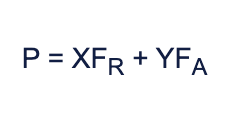
Where:
- F A = Axial (thrust) Load
- F R = Radial Load
- X = Radial Load Factor from table 1
- Y = Thrust Load Factor from table 1
To find the X and Y values, first calculate FA/FR and compare to the value of e in Table 1. Using the appropriate values for X and Y, substitute all known values into the Equivalent Radial Load equation. The result can then be used to determine the L10 life or compared to the radial load ratings in Table 2. If P is less than FR use P=FR If you have only axial (thrust) load, the equivalent radial load P = YFA where Y is taken from the column for values >e.
The magnitude and direction of both radial and thrust loads must be taken into account when selecting a housing. When pillow blocks are utilized, heavy loads should be directed thru the base. Where a load pulls the housing away from the mounting base, both the hold-down bolts and housing must be of adequate strength. Auxiliary load carrying devices (such as shear bars) are advisable for side or end loading of pillow blocks and radial loads for flanged units.
The effectiveness of the shaft attachment to carry a thrust load depends on proper tightening of the set screws, shaft tolerance and shaft deflections. It is advisable to use auxiliary thrust carrying devices (shaft shoulder, thrust collar, snap ring, etc.) to locate the bearing under heavier thrust loads or where extreme reliability is desired (see Table 3 for set screw information).
The shaft tolerances recommended below are adequate for normal radial and radial/thrust load applications. Where the applied radial load exceeds the Maximum Slip Fit Radial Load, a snug-to-light press fit of the shaft is required. Since the allowable load, especially at low RPM, is very large, the shaft should be checked to assure adequate shaft strength.
Shaft Tolerances:
|
Shaft Size |
Tolerance |
|---|---|
| UP TO 1 15⁄16" | +.0000 -.0005" |
| 2" TO 5" | +.0000 -.0010" |
Table 1 - Radial/Thrust Factors
|
Shaft |
e |
FA/FR ≤ e |
FA/FR > e |
Dynamic Capacity |
Static Capacity |
Seal Speed Limit RPM |
Maximum Allowable Slip Fit Radial Load (FR) LBS |
|||
|---|---|---|---|---|---|---|---|---|---|---|
| X |
Y |
X |
Y |
Lbs |
Newtons |
Lbs | ||||
|
1 7⁄16 - 1 1⁄2 |
0.28 | 1.0 |
2.4 |
0.67 |
3.6 |
16600 |
73400 |
18300 |
2800 |
2000 |
|
1 11⁄16 - 1 3⁄4 |
0.26 | 1.0 |
2.6 |
0.67 |
3.9 |
17300 |
77000 |
19800 |
2650 |
2100 |
|
1 15⁄16 - 2 |
0.24 | 1.0 |
2.8 |
0.67 |
4.2 |
19000 |
84500 |
22500 |
2400 |
2300 |
|
2 3⁄16 |
0.24 | 1.0 |
2.8 |
0.67 |
4.2 |
22400 |
99600 |
26500 |
2150 |
2700 |
|
2 7⁄16 - 2 1⁄2 |
0.24 | 1.0 |
2.8 |
0.67 |
4.2 |
33300 |
148000 |
41100 |
1800 |
4000 |
|
2 11⁄16 - 3 |
0.22 | 1.0 |
3.0 |
0.67 |
4.6 |
35500 |
158000 |
46800 |
1600 |
4200 |
|
3 3⁄16 - 3 1⁄2 |
0.23 | 1.0 |
2.9 |
0.67 |
4.4 |
56900 |
253000 |
76400 |
1300 |
6800 |
|
3 11⁄16 - 4 |
0.24 | 1.0 |
2.8 |
0.67 |
4.2 |
69900 |
311000 |
93300 |
1200 |
8400 |
|
4 7⁄16 - 4 1⁄2 |
0.25 | 1.0 |
2.7 |
0.67 |
4.0 |
91700 |
408000 |
126000 |
1100 |
11000 |
|
4 15⁄16 - 5 |
0.26 | 1.0 |
2.6 |
0.67 |
3.9 |
123000 |
547000 |
180000 |
900 |
14800 |
Table 2 - Easy Selection Table
|
Shaft |
L10 Life Hours |
Radial Load Ratings (Lbs.) at Various Revolutions per Minute |
|||||||||
|---|---|---|---|---|---|---|---|---|---|---|---|
| 50 |
100 |
250 |
500 |
1000 |
1200 |
1500 |
1750 |
2000 |
2500 |
||
|
1 7⁄16 - 1 1⁄2 |
5000 10000 30000 50000 100000 |
7365 5980 4300 3690 3000 |
5980 |
4545 |
3690 |
3000 |
2835 |
2655 2155 1550 1330 1080 |
2535 |
2435 1975 1420 1220 990 |
2275 |
|
1 11⁄16 - 1 3⁄4 |
5000 10000 30000 50000 100000 |
7675 6235 4485 3845 3125 |
6235 5065 3640 3125 2535 |
4735 3845 2765 2370 1925 |
3845 3125 2245 1925 1565 |
3125 2535 1825 1565 1270 |
2955 2400 1725 1480 1200 |
2765 2245 1615 1385 1125 |
2640 2145 1540 1320 1075 |
2535 2060 1480 1270 1030 |
2370 |
|
1 15⁄16 - 2 |
5000 10000 30000 50000 100000 |
8430 6845 4925 4225 3430 |
6845 |
5200 4225 3035 2605 2115 |
4225 |
3430 2785 2005 1720 1395 |
3245 |
3035 2465 1775 1520 1235 |
2900 |
2785 2260 1625 1395 1135 |
---- |
|
2 3⁄16 |
5000 10000 30000 50000 100000 |
9940 8070 5805 4980 4045 |
8070 |
6130 4980 3580 3070 2495 |
4980 |
4045 3285 2360 2025 1645 |
3830 |
3580 2910 2090 1795 1455 |
3420 |
3285 2665 1920 1645 1335 |
---- |
|
2 7⁄16 - 2 1⁄2 |
5000 10000 30000 50000 100000 |
14775 12000 8630 7405 6015 |
12000 |
9115 7405 5325 4570 3710 |
7405 |
6015 4885 3510 3015 2445 |
5695 |
5325 4325 3110 2665 2165 |
5085 |
4885 3965 2850 2445 1985 |
---- |
|
2 11⁄16 - 3 |
5000 10000 30000 50000 100000 |
15750 12795 9200 7895 6410 |
12795 |
9720 7895 5675 4870 3955 |
7895 |
6410 5205 3745 3210 2610 |
6070 |
5675 4610 3315 2845 2310 |
5420 |
---- ---- ---- ---- |
---- |
|
3 3⁄16 - 3 1⁄2 |
5000 10000 30000 50000 100000 |
25250 20510 14750 12655 10275 |
20510 |
15580 12655 9100 7805 6340 |
12655 |
10275 8345 6005 5150 4180 |
9730 |
---- ---- ---- ---- |
---- |
---- ---- ---- ---- |
---- |
|
3 11⁄16 - 4 |
5000 10000 30000 50000 100000 |
31020 25165 18120 15545 12625 |
25195 |
19140 15545 11180 9590 7790 |
15545 |
12625 10255 7375 6325 5140 |
11955 |
---- ---- ---- ---- |
---- |
---- ---- ---- ---- |
---- |
|
4 7⁄16 - 4 1⁄2 |
5000 10000 30000 50000 100000 |
40695 33050 23770 20395 16565 |
66050 |
25110 20395 14665 12585 10220 |
20395 |
16565 13455 9675 8300 6740 |
15680 |
---- ---- ---- ---- |
---- |
---- ---- ---- ---- |
---- |
|
4 15⁄16 - 5 |
5000 10000 30000 50000 100000 |
54585 44335 31885 27355 22220 |
44335 |
33680 27355 19675 16880 13710 |
27355 |
22220 18045 12980 11135 9045 |
---- |
---- ---- ---- ---- |
---- |
---- ---- ---- ---- |
---- |
Table 3 - Set Screw Information
|
Shaft Size |
Set Screw |
Tightening Torque |
Permissible Axial Load |
|
|---|---|---|---|---|
|
Inches |
No. | Size |
In-Lbs |
Lbs |
|
1 7⁄16 - 2 3⁄16 |
2 | 3⁄8"-24 |
250 |
515 |
|
2 7⁄16 - 3 1⁄2 |
2 | 1⁄2"-20 |
620 |
900 |
|
3 11⁄16 - 4 |
2 | 5⁄8"-18 |
1325 |
1200 |
|
4 7⁄16 - 5 |
4 | 5⁄8"-18 |
1325 |
2400 |